Type
Analysis
|
Element
|
Min
|
Max
|
|
Carbon
|
--
|
0.15
|
|
Nickel
|
36.0 nominal
|
|
Phosphorus
|
--
|
.006
|
|
Iron
|
Balance
|
|
Silicon
|
--
|
0.40
|
|
Manganese
|
--
|
0.60
|
|
Sulfur
|
--
|
0.004
|
|
Chromium
|
--
|
0.25
|
|
Cobalt
|
--
|
0.50
|
Description
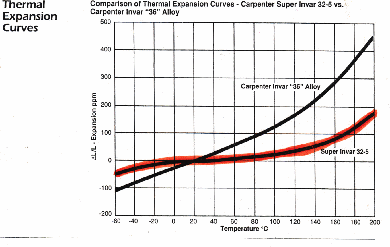
Invar 36 is a 36% nickel-iron alloy
possessing a rate of thermal expansion approximately one-tenth that
of carbon steel at temperatures up to 400°F(204°C)
Applications
This alloy has been used for
applications where dimensional changes due to temperature variation
must be minimized such as in radio and electronic devices, aircraft
controls, optical and laser system, etc.
Invar 36 alloy has also
been used in conjunction with high expansion alloys in applications
where a motion is desired when the temperature changes, such as in
bimetallic thermostats and in rod and tube assemblies for temperature
regulators.
Physical
Properties
|
Specific gravity ................ 8.05
Density
lb/cu in ......................... 0.291
kg/cu m ......................... 8055
Thermal conductivity
Btu-in/ft²/hr/°F ................ 72.6
W/m þ K .......................... 10.5
|
Electrical resistivity
ohm-cir mil/ft ................... 495
microhm-mm ...................... 820
Temperature coefficient of electrical
resistivity
per °F (70/212°F) ............. 0.0006
per °C (21/100°C) ............. 0.0011
|
Mean coefficient of thermal
expansion
|
Temperature
|
Coefficient
|
|
°F
|
°C
|
in/in/°F x
10(-6)
|
cm/cm/°C x
10(-6)
|
|
200
300
500
700
|
93
149
260
371
|
0.72
1.17
2.32
4.22
|
1.30
2.11
4.18
7.60
|

Curie temperature
°F ............................................................................................. 535
°C ............................................................................................. 279
Melt point
°F ........................................................................................... 2600
°C ........................................................................................... 1427
Specific Heat
Btu/lb þ°F ............................................................................. 0.123
kJ/kg þK ................................................................................ 0.515
Modulus of elasticity
Cold Rolled Strip Annealed Bar and Strip
psi x 10(6)........... 21.5........................... 20.5
MPa x 10(3) ....... 148 .......................... 141
Heat
Treatment<
Proper heat treatment is
critical to ensure that Invar 36 remains in a low internal stress
condition both throughout fabrication and during the service life of
the tool.
Recommended heat treatment parameters are shown in
table below
|
Heat
treatment
|
Time/Temp/Cool
|
Application
|
|
Full Anneal
|
1 hr at 1550°F
or
2hrs at 1350°C
air or oven cool
|
Following extensive
forming or welding
|
|
Stress
Relieve
Anneal (optional)
|
2 hrs at 600°F
air
or oven cool
|
1. Between rough and final
machining
2. Following minor weld repairs
|
Note:
A. For plate
thickness over 1.00", modify the heat treatment time at
temperature.
Add one hour per additional inch of thickness.
Example: 5 hrs at 600°F require to stress relieve anneal
4.00"
thick plate.
B. Invar 36 will
develop oxidation scale that increases as both heat treatment time
and temperature increase. For applications where sand blasting is not
an available process, a controlled atmospheric heat treatment oven will
be required.
C. Invar 36 must
be free of surface contaminants and cleaned before heat treatment.
D. Thermally
inducted tool distortion can be minimized by controlling heat up and
cool down during full anneal heat treatment. During heat up, first
stabilize the tool at 500°F and then increase by 50°F per
hour to full anneal temperature. During cool down, decrease the
temperature by 50°F per hour until temperature of the tool is
below 600°F. For tools exceeding 8 feet in length, weights may be
added to the ends and/or center of the tool as required to further
assist in maintaining contour.
Workability
Forging
The
principal precaution to observe in forging is to heat quickly and
avoid soaking in the furnace. Long soaking may result in a checked
surface due to absorption of sulfur from the furnace atmosphere
and/or oxide penetration. A forging temperature of 2000/2150°F is
preferred.
Coolant
It is
important to control heat build up, the major cause of warpage. A
suggested coolant would be Cool Tool. Cool Tool contains fatty esters
to reduce friction in the cutting zone and a refrigerant to remove
the heat generated by friction between the cutting tool and work
place.
Tooling
T-15
Alloy, such as Vasco Supreme-manufactured by Vanadium Alloys Company.
M-3 Type 2, such as Van Cut Type 2-manufactured by Vanadium Alloys
Company. Congo manufactured by Braeburn.
For machining with
carbide tools, a K-6 manufactured by Kennemetal, Firthie HA
manufactured by Firth Sterling, or #370 Carboloy could be used, or a
K2S manufactured by Kennemetal, or Firthie T-04 manufactured by Firth
Sterling would be satisfactory. One thing of prime importance is that
all feathered or wire edges should be removed from the tools. They
should be kept in excellent condition by repeated inspection.
Turning
If
steel cutting tools are used, try a feed of approximately .010"
to .012" per revolution and a speed as high as 35/FPM could
probably be attained. Some of the angels on the cutting tools would
be as follows:
End
cutting edge angle -Approximately 7°
Nose
radius -Approximately .005"
Side
cutting edge angle -Approximately 15°
Back
rake -Approximately 8°
Side
rake -Approximately 8°
When cutting off high
speed tools are better than carbide tools, and a feed of
approximately .001" per revolution should be used. The cutting
tools should have a front clearance of about 7° and a fairly big
tip--larger than 25° would be helpful.
Welding
Invar
36 can be welded by the convetional methods. Caution must be taken so
as not to overheat the molten metal. This will avoid spattering of the
molten metal and pits in the welded area. When filler rod is required
, Invarod has been used.
Drilling
When
drilling a 3/16" diameter hole, a speed of about 40/FPM could
possibly be used, and the feed should be about .002" to .0025"
per revolution, for a 1/2" hole, approximately the same speed
could be used with a feed of about .004" to .005" per
revolution. The drills should be as short as possible, and it is
desirable to make a thin web at the point by conventional methods. By
conventional methods, we mean do not notch or make a crank shaft
grinding. It is suggested that heavy web type drills with nitrided or
electrolyzed surfaces be used. The hole, of course, should be cleaned
frequently in order to remove the chips, which will gall, and also
for cooling. The drill should be ground to an included point angle of
118° to 120°
Reaming
Reaming
speeds should be haft the drill speed, but the feed should be about
three times the drill speed. It is suggested that the margin on the
land should be about .005" to .010", and that the chamfer
should be .005" to .010" and the chamfer angle about 30°.
The tools should be as short as possible, and have a slight face rake
of about 5° to 8°.
Tapping
In
tapping, a tap drill slightly larger than the standard drill
recommended for conventional threads should be used, because the
metal will probably flow into the cut. It is suggested that on
automatic machines, a two or three fluted tapping tool should be
used. For taps below 3/16", the two fluted would be best. Grind
the face hook angle to 8° to 10°, and the tap should have a
.003" to .005" chamfered edge. If possible, if binding
occurs in the hole in tapping, the width of the land may be too
great, and it is suggested that the width of the heel be ground down.
Again, it is suggested that nitrided or electrolyzed tools be used.
Speed should be about 20/FPM.
|
High
Speed Tool*
|
|
Turning
And
Forming
|
Cut-Off
Tool
|
1/16"
|
SFM
FEED
|
65
.0010
|
|
1/8"
|
SFM
FEED
|
67
.0012
|
|
1/4"
|
SFM
FEED
|
69
.0016
|
|
Tool
Width
|
1/2"
|
SFM
FEED
|
67
.0012
|
|
1"
|
SFM
FEED
|
63
.0010
|
|
1-1/2"
|
SFM
FEED
|
63
.0009
|
|
Drilling
|
Drill
Dia.
|
3/8"
|
SFM
FEED
|
43
.0030
|
|
3/4"
|
SFM
FEED
|
45
.0036
|
|
Reaming
|
Under 1/2"
|
SFM
FEED
|
57
.003
|
|
Over 1/2"
|
SFM
FEED
|
57
.0045
|
|
Threading
|
T.P.I
|
3-7½
8-15
|
SFM
SFM
|
8
10
|
|
Over 16
|
SFM
|
16
|
|
Tapping
|
T.P.I
|
3-7½
8-15
16-24
|
SFM
SFM
SFM
|
6
7
11
|
|
Over 25
|
SFM
|
16
|
|
Milling
|
|
SFM
FEED
|
35-70
.002-.005
|
|
Broaching
|
|
SFM
FEED
|
8-12
.001-.005
|
|
Turning
Single
Point
& Box Tools
|
High Speed Tools
|
SFM
FEED
|
60-65
.0029-.0043
|
|
Carbide Tools
|
SFM
FEED
|
160-215
.025-.080
|
*When using carbide
tools, surface speed feet/minute (SFM) can be increased between 2
and 3 times over the high speed suggestions. Feeds can be increased
between 50 and 100%.
Note: Figures used
for all metal removal operations covered are average. On certain
work, the nature of the part may require adjustment of speeds and
feeds. Each job has to be developed for best production results with
optimum tool life. Speeds or feeds should be increased or decreased
in small steps.
The information and
data presented herein are typical or average values and are not a
guarantee of maximum or minimum values. Applications specifically
suggested for material described herein are made solely for the
purpose of illustration to enable the reader to make his own
evaluation and are not intended as warranties, either express or
implied, of fitness for these or other purposes.
Applicable
Specifications
Invar 36 alloy meets the
requirement of specification Boeing D-33028.
| 

